
- English
- Español
- Português
- русский
- Français
- 日本語
- Deutsch
- tiếng Việt
- Italiano
- Nederlands
- ภาษาไทย
- Polski
- 한국어
- Svenska
- magyar
- Malay
- বাংলা ভাষার
- Dansk
- Suomi
- हिन्दी
- Pilipino
- Türkçe
- Gaeilge
- العربية
- Indonesia
- Norsk
- تمل
- český
- ελληνικά
- український
- Javanese
- فارسی
- தமிழ்
- తెలుగు
- नेपाली
- Burmese
- български
- ລາວ
- Latine
- Қазақша
- Euskal
- Azərbaycan
- Slovenský jazyk
- Македонски
- Lietuvos
- Eesti Keel
- Română
- Slovenski
- मराठी
- Srpski језик

Based on 8-inch silicon carbide single crystal growth furnace technology
2024-07-11
Silicon carbide is one of the ideal materials for making high-temperature, high-frequency, high-power and high-voltage devices. In order to improve production efficiency and reduce costs, the preparation of large-size silicon carbide substrates is an important development direction. Aiming at the process requirements of 8-inch silicon carbide(SIC) single crystal growth, the growth mechanism of silicon carbide physical vapor transport(PVT) method was analyzed, the heating system(TaC Guide Ring, TaC Coated Crucible, TaC Coated Rings, TaC Coated Plate, TaC Coated Three-petal Ring, TaC Coated Three-petal Crucible, TaC Coated Holder, Porous Graphite, Soft Felt, Rigid Felt SiC-coated Crystal Growth Susceptor and other SiC Single Crystal Growth Process Spare Parts are provided by VeTek Semiconductor ), crucible rotation and process parameter control technology of silicon carbide single crystal growth furnace were studied, and 8-inch crystals were successfully prepared and grown through thermal field simulation analysis and process experiments.
0 Introduction
Silicon carbide (SiC) is a typical representative of the third-generation semiconductor materials. It has performance advantages such as larger bandgap width, higher breakdown electric field, and higher thermal conductivity. It performs well in high temperature, high pressure and high frequency fields, and has become one of the main development directions in the field of semiconductor material technology. It has a wide range of application needs in new energy vehicles, photovoltaic power generation, rail transportation, smart grid, 5G communication, satellites, radars and other fields. At present, the industrial growth of silicon carbide crystals mainly uses physical vapor transport (PVT), which involves complex multi-physical field coupling problems of multi-phase, multi-component, multiple heat and mass transfer and magneto-electric heat flow interaction. Therefore, the design of the PVT growth system is difficult, and the process parameter measurement and control during the crystal growth process is difficult, resulting in the difficulty in controlling the quality defects of the grown silicon carbide crystals and the small crystal size, so that the cost of devices with silicon carbide as the substrate remains high.
Silicon carbide manufacturing equipment is the foundation of silicon carbide technology and industrial development. The technical level, process capability and independent guarantee of silicon carbide single crystal growth furnace are the key to the development of silicon carbide materials in the direction of large size and high yield, and are also the main factors driving the third-generation semiconductor industry to develop in the direction of low cost and large-scale. At present, the development of high-voltage, high-power and high-frequency silicon carbide devices has made significant progress, but the production efficiency and preparation cost of devices will become an important factor restricting their development. In semiconductor devices with silicon carbide single crystal as substrate, the value of substrate accounts for the largest proportion, about 50%. The development of large-size high-quality silicon carbide crystal growth equipment, improving the yield and growth rate of silicon carbide single crystal substrates, and reducing production costs are of key significance to the application of related devices. In order to increase production capacity supply and further reduce the average cost of silicon carbide devices, expanding the size of silicon carbide substrates is one of the important ways. At present, the international mainstream silicon carbide substrate size is 6 inches, and it has been rapidly advancing to 8 inches.
The main technologies that need to be solved in the development of 8-inch silicon carbide single crystal growth furnaces include: 1) Design of large-size thermal field structure to obtain a smaller radial temperature gradient and a larger longitudinal temperature gradient suitable for the growth of 8-inch silicon carbide crystals. 2) Large-size crucible rotation and coil lifting and lowering motion mechanism, so that the crucible rotates during the crystal growth process and moves relative to the coil according to process requirements to ensure the consistency of the 8-inch crystal and facilitate growth and thickness. 3) Automatic control of process parameters under dynamic conditions that meet the needs of high-quality single crystal growth process.
1 PVT crystal growth mechanism
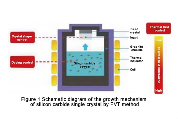
The PVT method is to prepare silicon carbide single crystals by placing the SiC source at the bottom of a cylindrical dense graphite crucible, and the SiC seed crystal is placed near the crucible cover. The crucible is heated to 2 300~2 400 ℃ by radio frequency induction or resistance, and is insulated by graphite felt or porous graphite. The main substances transported from the SiC source to the seed crystal are Si, Si2C molecules and SiC2. The temperature at the seed crystal is controlled to be slightly lower than that at the lower micro-powder, and an axial temperature gradient is formed in the crucible. As shown in Figure 1, the silicon carbide micro-powder sublimates at high temperature to form reaction gases of different gas phase components, which reach the seed crystal with a lower temperature under the drive of the temperature gradient and crystallize on it to form a cylindrical silicon carbide ingot.
The main chemical reactions of PVT growth are:
SiC(s)⇌Si(g)+C(s) (1)
2SiC⇌Si2C(g)+C(s) (2)
2SiC⇌SiC2(g)+Si(l,g) (3)
SiC(s)⇌SiC(g) (4)
The characteristics of PVT growth of SiC single crystals are:
1) There are two gas-solid interfaces: one is the gas-SiC powder interface, and the other is the gas-crystal interface.
2) The gas phase is composed of two types of substances: one is the inert molecules introduced into the system; the other is the gas phase component SimCn produced by the decomposition and sublimation of SiC powder. The gas phase components SimCn interact with each other, and a part of the so-called crystalline gas phase components SimCn that meet the requirements of the crystallization process will grow into the SiC crystal.
3) In the solid silicon carbide powder, solid-phase reactions will occur between particles that have not sublimated, including some particles forming porous ceramic bodies through sintering, some particles forming grains with a certain particle size and crystallographic morphology through crystallization reactions, and some silicon carbide particles transforming into carbon-rich particles or carbon particles due to non-stoichiometric decomposition and sublimation.
4) During the crystal growth process, two phase changes will occur: one is that the solid silicon carbide powder particles are transformed into gas phase components SimCn through non-stoichiometric decomposition and sublimation, and the other is that the gas phase components SimCn are transformed into lattice particles through crystallization.
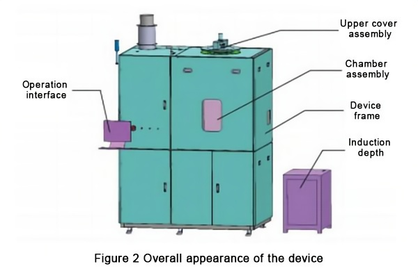
2 Equipment Design As shown in Figure 2, the silicon carbide single crystal growth furnace mainly includes: upper cover assembly, chamber assembly, heating system, crucible rotation mechanism, lower cover lifting mechanism, and electrical control system.
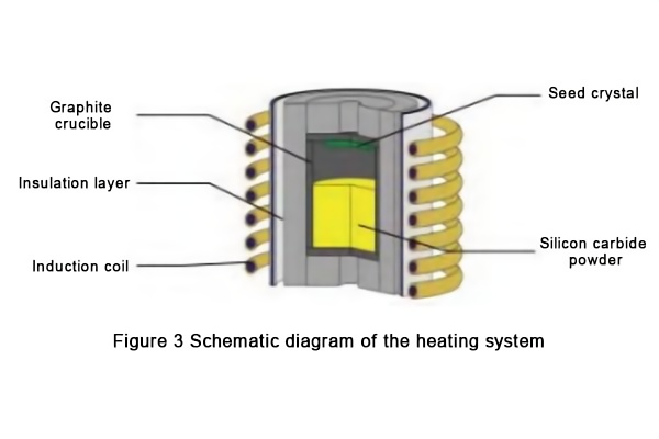
2.1 Heating System As shown in Figure 3, the heating system adopts induction heating and is composed of an induction coil, a graphite crucible, an insulation layer(rigid felt, soft felt), etc. When the medium frequency alternating current passes through the multi-turn induction coil surrounding the outside of the graphite crucible, an induced magnetic field of the same frequency will be formed in the graphite crucible, generating an induced electromotive force. Since the high-purity graphite crucible material has good conductivity, an induced current is generated on the crucible wall, forming an eddy current. Under the action of the Lorentz force, the induced current will eventually converge on the outer wall of the crucible (i.e., the skin effect) and gradually weaken along the radial direction. Due to the existence of eddy currents, Joule heat is generated on the outer wall of the crucible, becoming the heating source of the growth system. The size and distribution of Joule heat directly determine the temperature field in the crucible, which in turn affects the growth of the crystal.
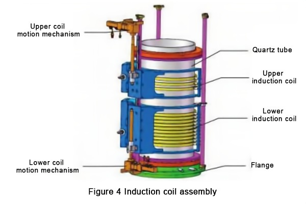
As shown in Figure 4, the induction coil is a key part of the heating system. It adopts two sets of independent coil structures and is equipped with upper and lower precision motion mechanisms respectively. Most of the electric heat loss of the entire heating system is borne by the coil, and forced cooling must be performed. The coil is wound with a copper tube and cooled by water inside. The frequency range of the induced current is 8~12 kHz. The frequency of the induction heating determines the penetration depth of the electromagnetic field in the graphite crucible. The coil motion mechanism uses a motor-driven screw pair mechanism. The induction coil cooperates with the induction power supply to heat the internal graphite crucible to achieve the sublimation of the powder. At the same time, the power and relative position of the two sets of coils are controlled to make the temperature at the seed crystal lower than that at the lower micro-powder, forming an axial temperature gradient between the seed crystal and the powder in the crucible, and forming a reasonable radial temperature gradient at the silicon carbide crystal.
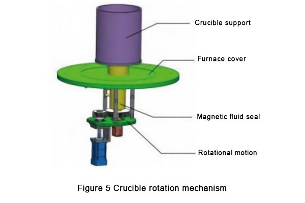
2.2 Crucible Rotation Mechanism During the growth of large-sized silicon carbide single crystals, the crucible in the vacuum environment of the cavity is kept rotating according to the process requirements, and the gradient thermal field and the low-pressure state in the cavity need to be kept stable. As shown in Figure 5, a motor-driven gear pair is used to achieve stable rotation of the crucible. A magnetic fluid sealing structure is used to achieve dynamic sealing of the rotating shaft. The magnetic fluid seal uses a rotating magnetic field circuit formed between the magnet, the magnetic pole shoe and the magnetic sleeve to firmly adsorb the magnetic liquid between the pole shoe tip and the sleeve to form an O-ring-like fluid ring, completely blocking the gap to achieve the purpose of sealing. When the rotational motion is transmitted from the atmosphere to the vacuum chamber, the liquid O-ring dynamic sealing device is used to overcome the disadvantages of easy wear and low life in solid sealing, and the liquid magnetic fluid can fill the entire sealed space, thereby blocking all channels that can leak air, and achieving zero leakage in the two processes of crucible movement and stopping. The magnetic fluid and crucible support adopt a water-cooling structure to ensure the high-temperature applicability of the magnetic fluid and crucible support and achieve the stability of the thermal field state.
2.3 Lower cover lifting mechanism
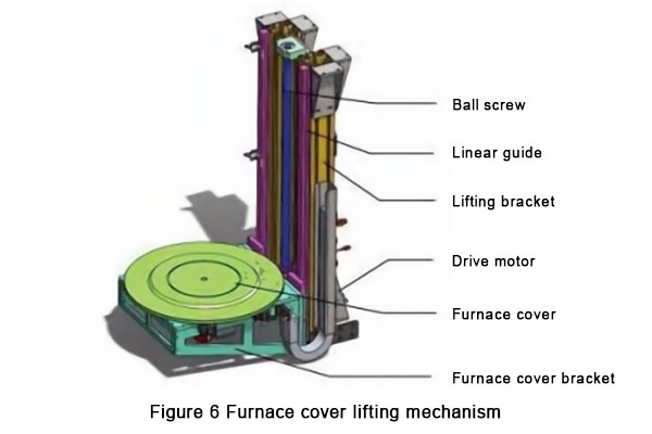
The lower cover lifting mechanism consists of a drive motor, a ball screw, a linear guide, a lifting bracket, a furnace cover and a furnace cover bracket. The motor drives the furnace cover bracket connected to the screw guide pair through a reducer to realize the up and down movement of the lower cover.
The lower cover lifting mechanism facilitates the placement and removal of large-sized crucibles, and more importantly, ensures the sealing reliability of the lower furnace cover. During the whole process, the chamber has pressure change stages such as vacuum, high pressure, and low pressure. The compression and sealing state of the lower cover directly affects the process reliability. Once the seal fails under high temperature, the whole process will be scrapped. Through the motor servo control and limit device, the tightness of the lower cover assembly and the chamber is controlled to achieve the best state of compression and sealing of the furnace chamber sealing ring to ensure the stability of the process pressure, as shown in Figure 6.
2.4 Electrical control system During the growth of silicon carbide crystals, the electrical control system needs to accurately control different process parameters, mainly including the coil position height, crucible rotation rate, heating power and temperature, different special gas intake flow, and the opening of the proportional valve.
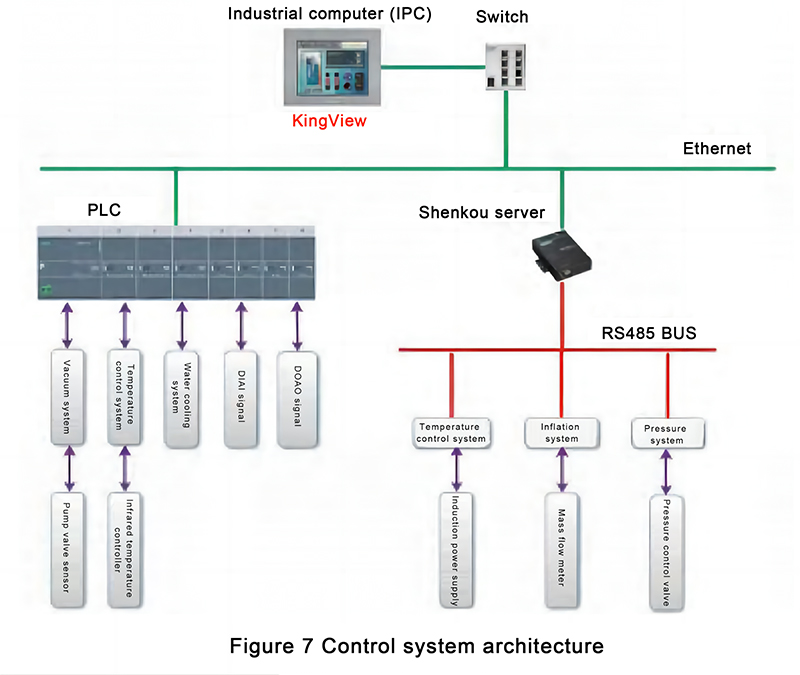
As shown in Figure 7, the control system uses a programmable controller as a server, which is connected to the servo driver through the bus to realize the motion control of the coil and crucible; it is connected to the temperature controller and flow controller through the standard MobusRTU to realize real-time control of temperature, pressure and special process gas flow. It establishes communication with the configuration software through Ethernet, exchanges system information in real time, and displays various process parameter information on the host computer. Operators, process personnel and managers exchange information with the control system through the human-machine interface.
The control system performs all field data collection, analysis of the operating status of all actuators and the logical relationship between the mechanisms. The programmable controller receives the instructions of the host computer and completes the control of each actuator of the system. The execution and safety strategy of the automatic process menu are all executed by the programmable controller. The stability of the programmable controller ensures the stability and safety reliability of the process menu operation.
The upper configuration maintains data exchange with the programmable controller in real time and displays field data. It is equipped with operation interfaces such as heating control, pressure control, gas circuit control and motor control, and the setting values of various parameters can be modified on the interface. Real-time monitoring of alarm parameters, providing screen alarm display, recording the time and detailed data of alarm occurrence and recovery. Real-time recording of all process data, screen operation content and operation time. The fusion control of various process parameters is realized through the underlying code inside the programmable controller, and a maximum of 100 steps of process can be realized. Each step includes more than a dozen process parameters such as process operation time, target power, target pressure, argon flow, nitrogen flow, hydrogen flow, crucible position and crucible rate.
3 Thermal field simulation analysis
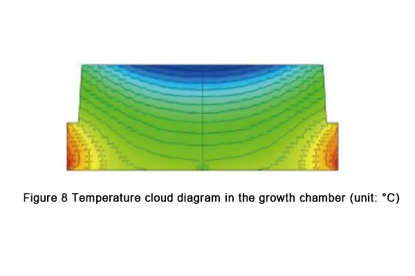
The thermal field simulation analysis model is established. Figure 8 is the temperature cloud map in the crucible growth chamber. In order to ensure the growth temperature range of 4H-SiC single crystal, the center temperature of the seed crystal is calculated to be 2200℃, and the edge temperature is 2205.4℃. At this time, the center temperature of the crucible top is 2167.5℃, and the highest temperature of the powder area (side down) is 2274.4℃, forming an axial temperature gradient.
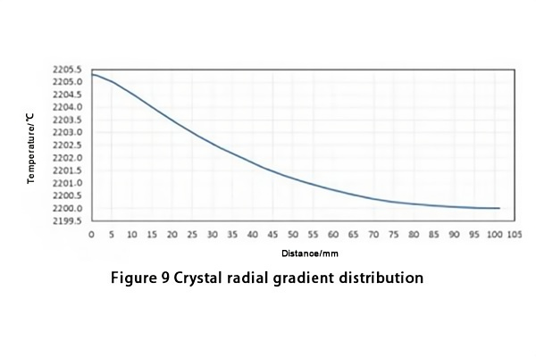
The radial gradient distribution of the crystal is shown in Figure 9. The lower lateral temperature gradient of the seed crystal surface can effectively improve the crystal growth shape. The current calculated initial temperature difference is 5.4℃, and the overall shape is nearly flat and slightly convex, which can meet the radial temperature control accuracy and uniformity requirements of the seed crystal surface.
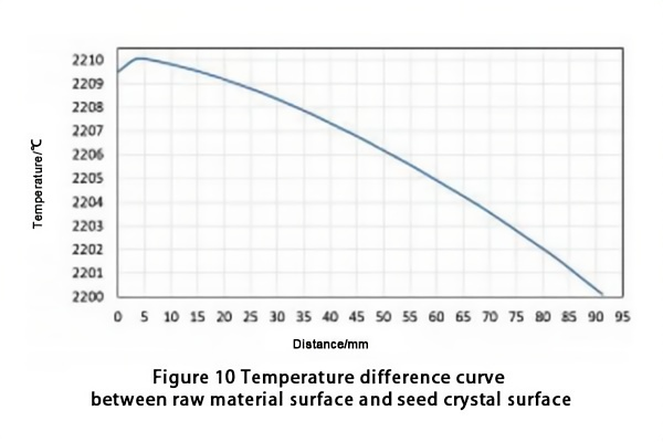
The temperature difference curve between the raw material surface and the seed crystal surface is shown in Figure 10. The center temperature of the material surface is 2210℃, and a longitudinal temperature gradient of 1℃/cm is formed between the material surface and the seed crystal surface, which is within a reasonable range.
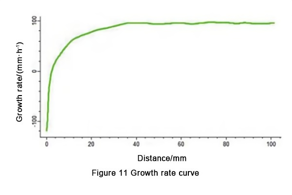
The estimated growth rate is shown in Figure 11. Too fast growth rate can increase the probability of defects such as polymorphism and dislocation. The current estimated growth rate is close to 0.1 mm/h, which is within a reasonable range.
Through thermal field simulation analysis and calculation, it is found that the center temperature and edge temperature of the seed crystal meet the radial temperature gradient of the crystal of 8 inches. At the same time, the top and bottom of the crucible form an axial temperature gradient suitable for the length and thickness of the crystal. The current heating method of the growth system can meet the growth of 8-inch single crystals.
4 Experimental test
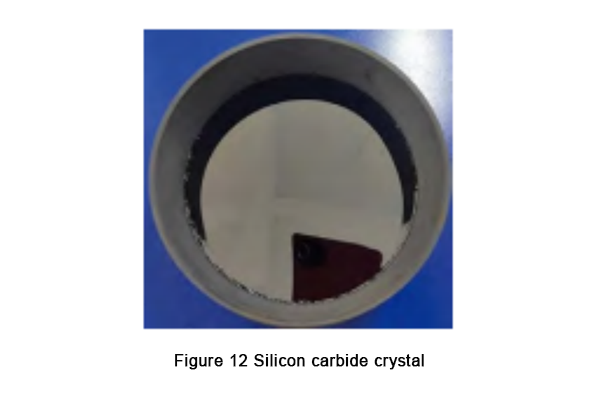
Using this silicon carbide single crystal growth furnace, based on the temperature gradient of the thermal field simulation, by adjusting the parameters such as the crucible top temperature, cavity pressure, crucible rotation speed, and the relative position of the upper and lower coils, a silicon carbide crystal growth test was carried out, and an 8-inch silicon carbide crystal was obtained (as shown in Figure 12).
5 Conclusion
The key technologies for the growth of 8-inch silicon carbide single crystals, such as gradient thermal field, crucible motion mechanism, and automatic control of process parameters, were studied. The thermal field in the crucible growth chamber was simulated and analyzed to obtain the ideal temperature gradient. After testing, the double-coil induction heating method can meet the growth of large-sized silicon carbide crystals. The research and development of this technology provides equipment technology for obtaining 8-inch carbide crystals, and provides equipment foundation for the transition of silicon carbide industrialization from 6 inches to 8 inches, improving the growth efficiency of silicon carbide materials and reducing costs.